PET (Poly Ethelene Terephthalates) Bottles are generally used in for Bottled Water / Packaged Water Industry. These machines are combination of Two Main Parts, Infrared Heating Section & Blowing Section. Machine are available in different capacities and types like Auto & Semi Auto.
Traditionally, pipe water distributed by the municipalities has been the trusted water supply for drinking purposes. In the earlier days, water available from the wells and springs used to be considered safe and was stored in earthen pots or brass containers. This water was considered safe for drinking and serving to guests and visitors. The tradition and style of serving drinking water, in India, has however changed quite dramatically during the last decade. Almost a decade ago, the introduction of bottled water or “packaged mineral water” has changed the tradition of serving and consuming drinking water. This has ushered in very strongly, the use of polymers or plastics as materials for water storage and distribution.
PACKING REQUIREMENTS
It is well known that drinking water should be packed in clean, colourless, odourless, clear, tamperproof containers, which are hygienically safe. Much of the water is packaged in similar bottles as carbonated soft drinks, and would, therefore, carry many of the same requirements.
a. STRENGTH
Unlike carbonated drinks, the bottles filled with still water need only enough strength to hold water and to survive impact.
b. COLOR & CLARITY
Clarity is one of the most important requirements and is the main reason why clear bottles of plastics are used. A resin with higher levels of co-polymer adds to the clarity. As regards the light blue colour in the bottles, this is permissible for one time use bottles. However in India, the BIS (Bureau of India Standards) have prescribed colourless bottles for multi trip/reusable containers. Since currently almost all the bottlers use blue coloured containers, studies have commenced at IIP to establish whether blue colour helps to reduce the UV effect and the percentage of blue colour that could be considered to be added without affecting the clarity of the bottle.
c. PURITY
Because water is a flavorless product, using a plastic that remains tasteless and odourless is imperative.
d. CERTIFICATION
To prevent adulteration, the quality of the bottle and its sealing drew great attention and concern. The standardization of the quality of the water and the bottles was not thought of earlier. There was a concern whether mushrooming brands in packaged drinking water would really ensure quality and safety. The provisions of mandatory BIS certification and that of Prevention of Food Adulteration Act (PFA) have brought in assurance to the consumers that packaged drinking water is trustworthy. The Indian Standard IS: 14543 – 1998 prescribes the quality and safety requirements of packaged drinking water.
PLASTIC BOTTLE MANUFACTURING PROCESS:
PET Preforms is the basic Raw material used in manufacturing of bottles. The machines used for manufacturing of such kind of bottles are known as STRETCH BLOW MOULDING MACHINES. The name in itself simplifies the meaning of the machine. The basic process includes heating of the Preform to a suitable temperature, Chilling its neck, Putting it in a Mould designed as per the shape & size required and blowing it with required air pressure.
The machine can be categorized in 2 different categories:
a. SEMI AUTOMATIC WITH AUTODROP
b. FULLY AUTOMATIC MACHINE
SEMI AUTOMATIC STRETCH BLOW MOLD MACHINE:
The different modules of the machine are:
a. Infrared Heating Module:
This module consists of a chain type rotating conveyor which passes through a tunnel. The tunnel consists of Infrared heating Lamps controlled by the main PLC of the machine. The temperature of the tunnel is maintained constant using thermostat devices. The wattage and no. of IR Lamps required are designed as per the capacity of the machine. A chilled water flow is maintained continuously through a tube which passes parallel to the chain conveyor and is near to the neck of the perform to ensure that the neck of the perform does not get deformed due to heat. The length of the tunnel and the conveyor is designed as per the capacity requirement of the machine. The Preforms are kept rotating around its axis so that the heat from the lamp is uniformly distributed and is effected to all the parts of the perform. The Preforms are loaded & unloaded manually on & from the conveyor. The Preform thus heated now acquires a required elasticity to be blown. The heated performs are not allowed to cool because if the perform cools, due to atmospheric reaction the perform turns white and loses its transparency and hence have to be blown immediately after heating.
b. Mold:
Mold forms a vital part in this process. The heated perform during blowing will take the shape of the mold. The mold closure has to be designed properly so that the air does not escape during the process. The mold is actually designed in two parts this two parts form the two halves of the bottle if cut vertically. One mold is fixed to the blowing module fixed base plate and the other fixed to the moving base plate. The movement of the Moving blasé plate is done with the help of hydraulic cylinders wherein the Piston of the cylinder is connected to the moving base plate. As the piston performs it to & fro action the mold fixed to the piston opens and closes with the other half of the mold. The placement of mold on both the base plates have to be very correct and precise so that the line mark on the bottle does not come once the bottle is blown. The mold are generally made up of aluminum alloy and are diamond finished internally to get smooth curves and finish to the mold. They may be single cavity (cavity is the gap between two halves of the mold), two, four, six cavity etc. Generally two cavity mold are used with semi automatic machines.
c. Blowing Module:
This module consists of pneumatic cylinders which operate a stretch rod, and hydraulic cylinders which initiate the opening and closing of the molds. Mold also forms a vital part in blowing. The heated performs are put in the mold and are blown using required air pressure. The heated performs have to be loaded in the mold manually and also unloaded manually. The perform is locked into the notch of the mold which is fixed to the base plate in the module (at this time the mold is open), the operator pins the blow button and the mold closes and the stretch rod is inserted in the Preform with the help of pneumatic cylinders. The rod stretches the heated perform to the base of the mold and then pressurized air is passed through the central opening in the stretch rod that blows the perform towards the walls of the mold hence resulting in an bottle derived to the shape of the mold. Once the bottle is blown the mold opens and the bottle falls down. The opening of the mold also unlocks the bottle from the notch in the mold. This completes one cycle of operation. The operating time of the cycle is designed as per the capacity required however the same is again dependant on human efficiency and the time required for a human to collect the prefrom from the heating conveyor and place it in the mould. Thus the timing can never be guaranteed in such operations and can be established theoretically only.
d. Chiller:
Air cooled or Water Cooled chiller of suitable capacities are used to chill the water during the Preform heating Process. This is mainly used to protect the neck of the perform from getting deformed due to heat. Deformed neck will not fit in the notch of the mold and hence blowing will not be proper moreover if the neck deforms the capping of the bottle will not happen as the cap will not get threaded on the threads of the bottle.
e. Compressor, Drier & Air Piping’s:
Suitable compressor High Press or Low pressure of required CFM as per the capacity is required to generate required air pressure to blow the bottles. Inefficient source of Air pressure may result in improper blowing of bottles. The air is also quite important in this case, if any foreign particle or oil or moisture is present in the air it may choke up the nozzles of the blower and most importantly it will adhere to the walls of the bottle and the bottle will loses its required transparency. The bottle will mot probably appear dull after blowing and lose its shine. Hence the air has to be properly filtered using a FRL unit and the moisture has to be completely taken out of the air for this purpose a Drier is required of suitable CFM capacity as per the compressor. The air vents and piping’s have to be done from the compressor to the drier and from the drier to the Blowing unit. These piping’s have to done as per the recommendations from the compressor supplier and have to generally done using GI or copper pipes. It is always recommended that the compressor and Blowing unit and all other ancillaries have to be maintained in close vicinity of each other to avoid big piping cost and also to avoid excessive pressure drop in the air flow. Longer the distance more will be the pressure drop resulting in unsatisfactory performance of the machine.
Since the above modules adopt manual interferences on large scale i.e. from Putting the performs on the heater , collecting the same and again loading it on the blow machine and again un loading it the time required for this operations cannot be ascertained practically and is 100% dependant on the efficiency of the operator. Thus this type of arrangement is called SEMI AUTOMATIC Blowing Technique and the machine so called by this name.
SEMI AUTOMATIC STRETCH BLOW MOLD MACHINE AUTO DROP:
All the forms and operating modes in these category remain the same as per the Semi Auto module the only difference lies in the mold and the stretch rod.
Here the mold is in two halves but the bottom of the mold is which will be in fact the bottle base will also open enabling the bottle to glide down automatically once it has been blown. The Stretch rod also does not retract immediately after blowing but retracts after a couple of seconds enable the bottle to fall down after the mold opens. Such arrangement reduces time in unloading of the bottle from the mold once it has blown and reduces the effort of the operator operating the machine. Since the cycle time is reduced we can produce more bottles in the same capacity of the machine used with semi auto version. The mold cost in this case is however on higher side and is of different arrangement.
Both the above versions are used extensively in the industry today, semi auto versions are now getting replaced by the Auto-drop versions because of higher efficiency values and good returns on investment. The basic range of these machines in terms of production capacity are from 600 BPH to a max. of 1800BPH (theoretical range) and in terms of bottle sizing an individual machine can blow from 60 ml to 2000ml in a single machine by effecting changes in the perform and the mold. 5000 ml can also be blown with slight changes in the machine
FULLY AUTOMATIC STRETCH BLOW MOLD MACHINE:
The figure below illustrates a typical Automatic Machine:
As seen in the figure above all the operations we saw in the Semi auto version is done with the help of atomization. All the operations in this case are automated and are programmed.
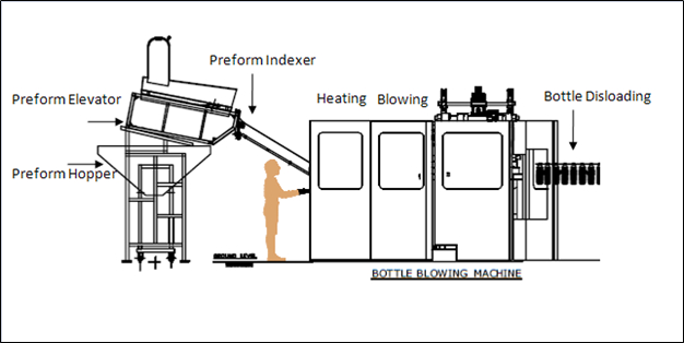
Herein the Preforms are put in a Preform Hopper which is designed to hold performs for at least 2 hours of the rated capacity of the machine. The Hopper is designed in such a way that all the performs slide down at a single point in the hopper due to gravity so that each and every perform from the hopper can be taken for process.
This hopper has a Preform Elevator which is a Stack type elevator which elevates a min of 2 to 3 preforms at a single time to avoid congestion at the indexer. The elevated performs may be in any direction hence they have to be oriented properly so that they can be fed to the in feed line on to the heating conveyor. Proper orientation means neck up and bottom down. To facilitate this a mechanism is used which is called the indexer. The indexer is an mechanically rotating shaft with wings having a notch. This notch catches the ring on the neck of the perform and orients it in required direction.
This indexed performs then pass on through the sliding neck holders. Neck holders are nothing but two plates aligned parallel to each other with a gap in between which allows passage of the perform in uniform direction.
This performs are now loaded on to the heating conveyor using robotic type arms which lift the perform by their neck ring and load it on to the chain conveyor. This perform now pass through the Infra Red Heating tunnels (one or more depending upon the capacity of the machine). The tunnels have almost the same kind of arrangement as in the semi automatic version.
The Heated Preforms are now again unloaded from the heating conveyor using robotic arms and are loaded on to the Mold sets. The no. of arms for loading the perform and the no. of tunnels and the no. of mold cavity are same for a given capacity of machine. Which means the cycle time required to blow one bottle is multiplied in no. of operating lines thus getting more bottles in one cycle time. The mold set blows this bottles and are unloaded by other robotic arm on to the unloading conveyor where they are ready to be fed to the filling line conveyor.
Since all the actions in these machines are controlled and have no manual interference we can establish a practical cycle time limit and hence these machines are more efficient with higher rates of productivity. The range of capacity and size of bottle can be programmed in the machine. The cost of molds in these machines are very high. For different size of the bottle different molds have to be used.
The basic range of these machines in terms of production capacity is from 2400 BPH to a max. of 4600BPH (Practical range) , and in terms of bottle sizing an individual machine can blow from 60 ml to 2000ml in a single machine by effecting changes in the perform and the mold. Higher ranges of machines are also available up to 20000BPH with rotary mechanism.
These machines are used at higher operating speeds and can be interlinked to the filling lines to achieve complete atomization of the process right from producing the bottles to Rinsing, Filling & Capping of the same. Since there is no Manual Interference strict and 100% hygienic requirements can be fulfilled.
COMPARISON BETWEEN ALL THE TWO CATEGORIES
| Comparison Points | Auto Drop | Fully Automatic |
| Min. Capacity | 800 BPH | 2400 BPH |
| Max. Capacity | 1800 BPH | 20000 BPH |
| Investment | High Approx. 8 Lacs for Min. capacity | Very High Approx. 40Lacs for Min. capacity |
| Power Requirement | Low Min. 35 H.P. | High Min. 60 H.P. |
| Labor Requirement | Min. 1 Skilled + 3 Unskilled Labor | 1 Skilled Operator + 1 Unskilled Labor |
| M/c Area Requirement | Low Min. 150 sq ft | High Min. 250 sq ft |
| Efficiency | Dependant on Operator | 99 .9% Efficient |
| Quality of Bottles | Good | Excellent |
| Hygiene | Low due to human interference | High due to no human interference |
| Operating Speeds | Can be used with moderate capacity plants with medium operating speeds | Generally used with higher operating speeds for high capacity plants |
| Mold Cost | Moderate | High |